Here we are, after several months of silence, I’m giving you out the schémathics of Parki.
…
…
You thought I was really going to give them to you?? Lol!!
I might consider it if you ask though… ;)
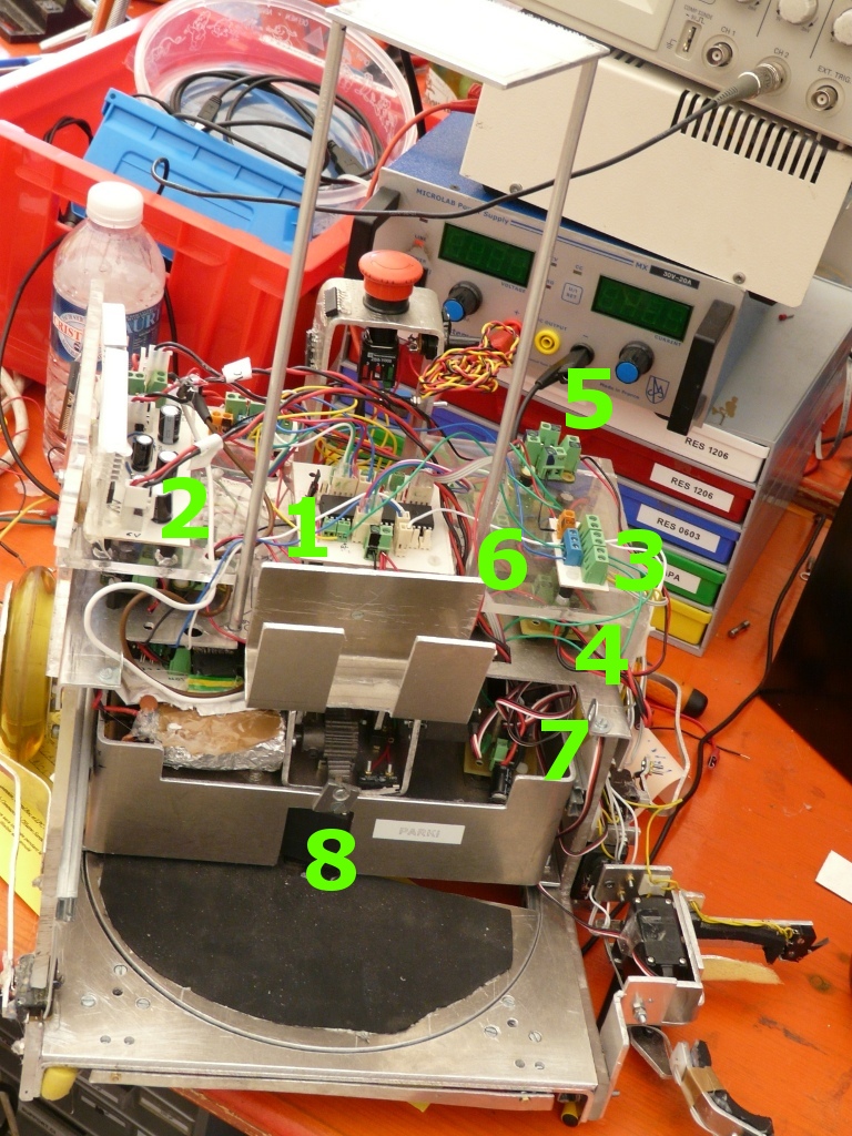
Let’s talk about more serious stuff. Parki’s core has 12 circuit boards which are :
- The motherboard (1) : a Pic18f4680 as the core/brain of the robot and lots of connectors for the other circuit boards.
- The Power Supply (2) : contains three high current capable voltage outputs : 5V for the logic, 6V for the servos and 19V for the motors.
- 2 three channel input boards (3) : they work as an interface between the micro-controller and the Bumpers (Contact sensors).
- 19V Power distributor board (4) : used to connect the output of the power supply and to distribute it to the motors.
- three 5V Power distributor boards (5) : one of them powers the motor boards, the others connected with a cable switch in between. When the cable is disconnected, the logic circuits are turned on and the robot starts moving.
- Two Stepper Motor Boards (6) : uses a SN754410 as motor driver. However, we burnt the IC and we didn’t have a replacement, so we changed to another IC the day of the contest.
- Servos distributor (7) : interface the servos, the micro-controller and the power supply.
- Line scanner (8) : an array of 14 IR sensors (QRD1114) scans the terrain to find lines under the robot. The purpose was to increase robot’s position accuracy. However we already had a very good one so we didn’t use this board in the end.
The following pictures illustrate Parkis electronic system.

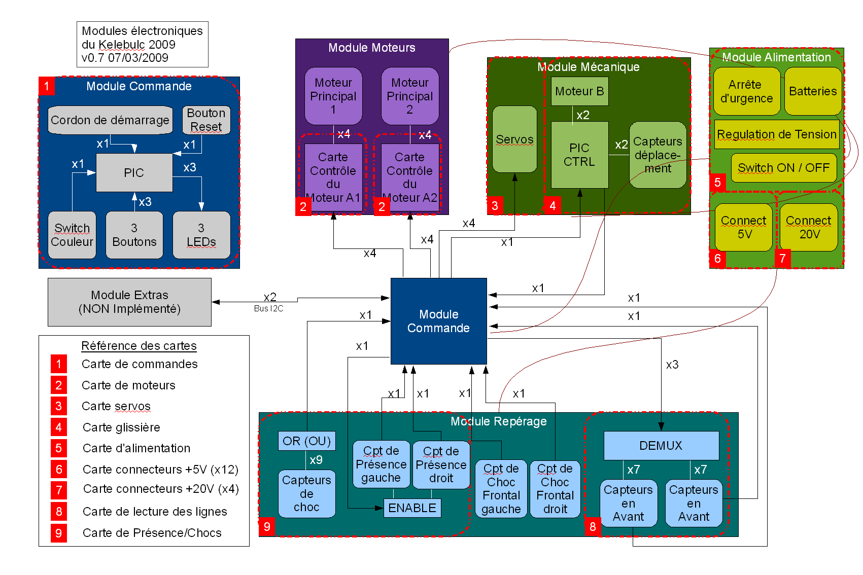
And finally a schéma that specifies all the connections between the electronic boards.
PS : it’s in french and some small changes were made in the final version.
