
The development of this robot was halted during the summer holidays, however the project got really advanced in July, where with only a single month of work, results were already visible.
As I’ve already said in an older post, I first defined what I wanted the robot to do, then I started the “real” stuff ;):
The robot was (is) developed in three main phases:
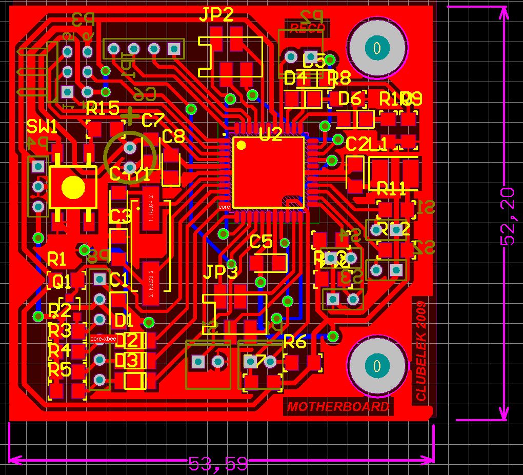
I first chose every component knowing in advance which circuit boards I wanted to create. Then, I developed the electronic schematics, and finally designed the PCBs (Printed Circuit Boards). The following image shows result of one of the boards :
Secondly, I built almost all the circuits. It’s not an easy task as it requires a lot of time and patience; for example the same board shown above, soldered with (almost) all the components looks like this:
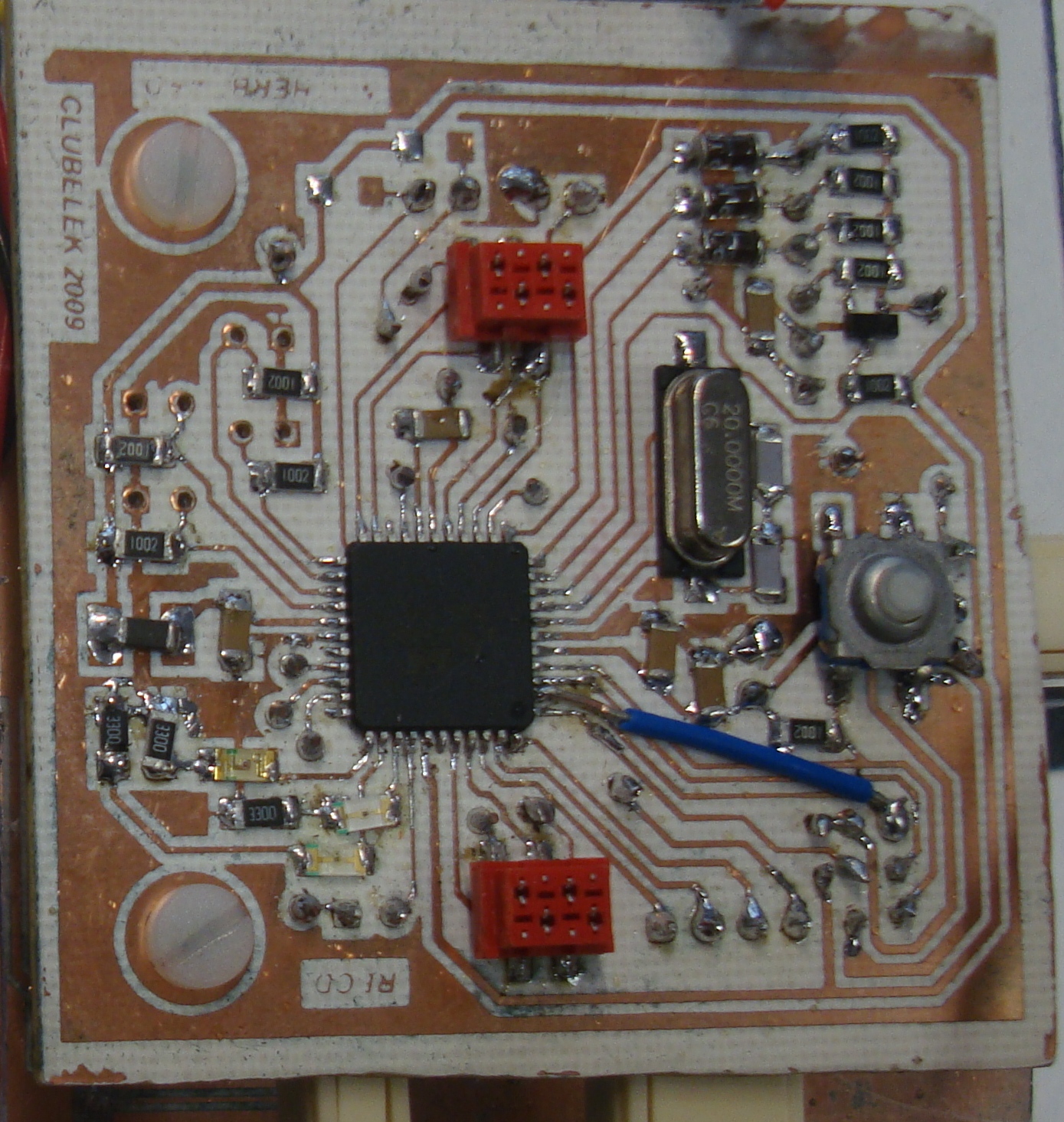
I must admit this PCB is far from good, but as this is just a prototyping version, it just matters if it works. :P
The final phase was the mechanical development which was made by Joël Teixeira (Tatos), wich was obviously followed by the board placement and connection, the robot is almost physically completed and looks like this:
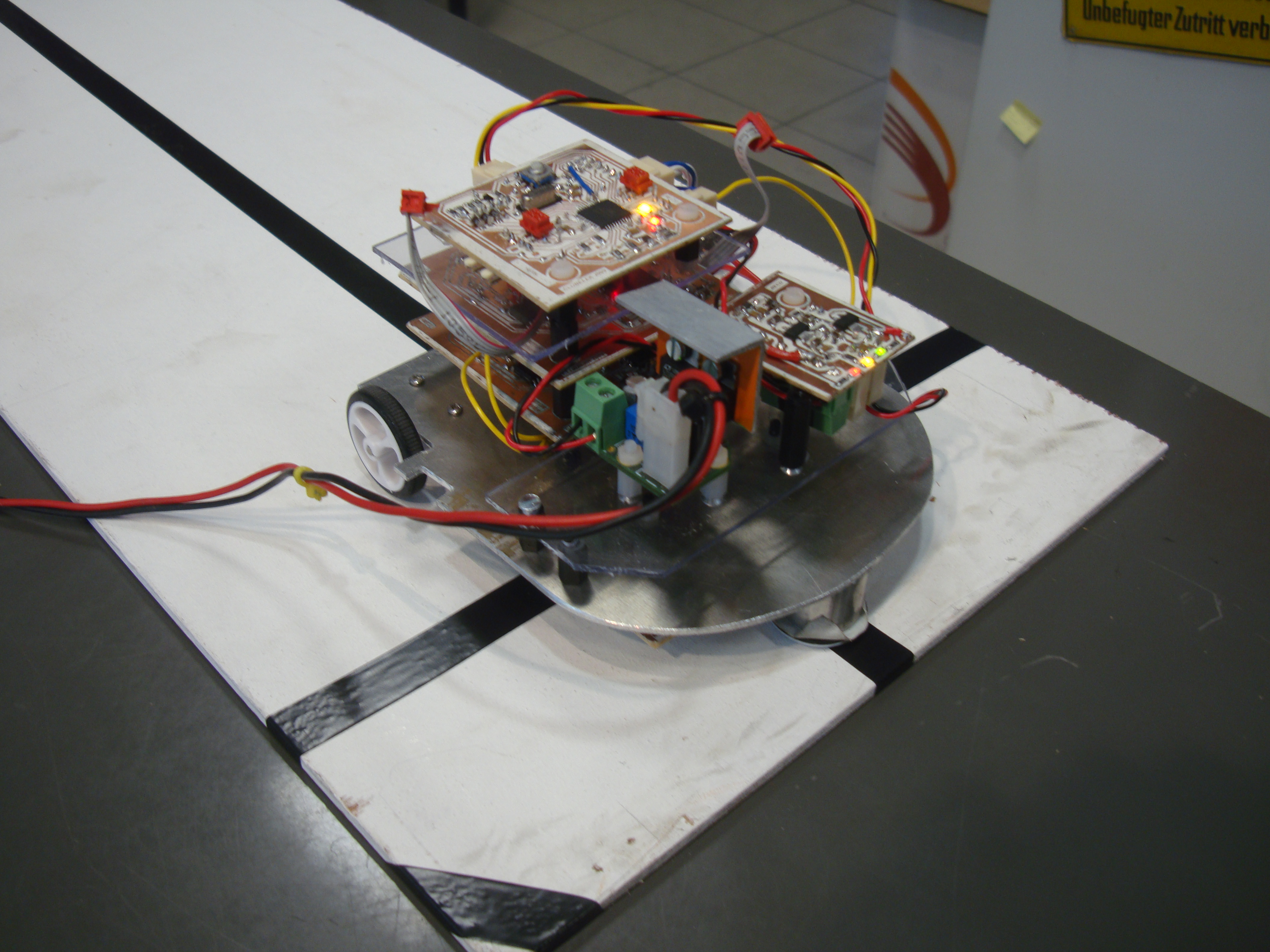
We’re just missing the wireless module and the robot will be complete. The programming however is far from finished. The line following algorithm has been coded and tested, it works like a charm. We’re using the very well known PID algorithm to follow the line, although we’re just using the “P” term in the video, it works really nice ;)
In the following posts, I’ll explain how some of the technology present in this robot works.
Keep tuned.